
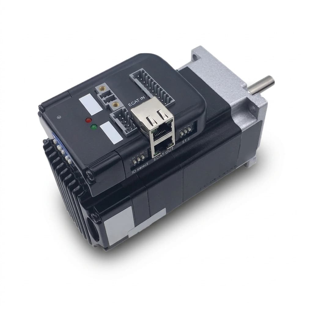
Bus-Controlled Stepper Motors: EtherCAT, CANopen, and Modbus RTU vs. Pulse/Direction Sourcing Guide
Compare bus-controlled stepper motors: EtherCAT, CANopen, Modbus RTU vs. pulse/direction. Check PLC compatibility, wiring costs, and RFQ acceptance criteria.
Selection summary
- Bus-controlled stepper motors: Compare complete machine cost, including controller hardware, motion licenses, wiring, commissioning, and service access. A fieldbus drive premium can be justified, but savings depend on the actual design.
- EtherCAT: Shortlist it for coordinated axes when the master and drives support the required cyclic modes and timing. Distributed clock synchronization is distinct from mechanical positioning accuracy.
- CANopen: Shortlist it for local profile moves or coordinated motion that fits a calculated CAN traffic budget. Modbus RTU: Use it for parameter changes and independent moves unless additional synchronization is explicitly documented.
- Pulse/direction: Keep it on the shortlist for existing controllers and simpler machines. Approve any bus alternative only after matching firmware, description files, modes, and fault behavior to your PLC.
In automated machine design, machine builders and original equipment manufacturers (OEMs) face an architectural transition: replacing legacy discrete pulse-and-direction (Step/Dir) stepper motor drives with digital industrial fieldbus networks. For decades, the standard method for controlling a NEMA stepper motor was firing high-frequency square-wave pulses from a PLC or motion card to an optocoupled driver.
Discrete Step/Dir hardware can have a low purchase price per driver, while dedicated pulse channels and signal wiring add cost as axis count increases. Pulse/direction itself carries commands, but drives can still provide separate alarm, in-position, encoder, or serial diagnostic outputs. Fieldbus makes richer diagnostics available through one network only when the selected drive actually exposes those values.
To solve these bottlenecks, industrial automation has transitioned toward standardized communication buses: EtherCAT, CANopen, and Modbus RTU. However, procurement teams and engineering managers often struggle to reconcile the higher initial unit cost of a bus-type drive with the total landed machine economics.
This technical sourcing guide delivers a total cost of ownership (TCO) evaluation, protocol deep-dive, hardware implementation boundary review, and a three-phase OEM procurement checklist to help engineering buyers select the optimal drive architecture for their motion platforms.
Published and reviewed: 2026-10-27. Scope: Global, English-language sourcing guidance for machine builders evaluating NEMA 11–34 hybrid steppers and nominal 24–80 V DC drive systems. Phase count, supply range, motor current, torque at operating speed, and environmental ratings must be verified for each motor/drive pair; a NEMA frame size specifies neither electrical compatibility nor torque. Cost figures below are hypothetical USD planning inputs, not supplier quotations or measured customer results. This guide does not qualify a machine's stopping performance or functional safety.
Preparing an RFQ? Send your axis count, PLC model, required cycle time, and load profile for a compatibility review.
1. Total Cost of Ownership (TCO): Component Price vs. Landed System Cost
Compare quotes at the machine level. The following hypothetical four-axis example assumes a controller already equipped with a compatible fieldbus master and motion license, but needing two additional pulse-output modules for Step/Dir. It is a reproducible budgeting worksheet, not a market price survey; use your own supplier quotes and assembly estimates.
| Cost element (USD, four axes) | Discrete Step/Dir | Fieldbus alternative |
|---|---|---|
| Four drives: assumed $30 vs. $75 each | $120 | $300 |
| Two additional pulse-output modules at $190; existing licensed bus master | $380 | $0 incremental |
| Control signal wiring / network patch cables | $80 | $24 |
| Signal wiring labor: 4.5 vs. 1.0 hours at $50/hour | $225 | $50 |
| Additional signal terminal blocks / rail allowance | $45 | $0 incremental |
| Signal harness inspection allowance | $60 | $15 |
| Total of listed items | $910 | $389 |
Calculation: Step/Dir = 120 + 380 + 80 + 225 + 45 + 60 = $910. Fieldbus = 300 + 0 + 24 + 50 + 0 + 15 = $389. The assumed difference is $521 (57.3% of $910). Any additional bus master, software, commissioning, or cable expense reduces that difference dollar for dollar; more than $521 of additional bus costs reverses the result.
Excluded from both columns: Motors, power supplies, phase/encoder wiring, protective devices, safety hardware, taxes, shipping, and service costs. Include these in the final installed-cost comparison. Power and safety terminals remain necessary with fieldbus. If an existing PLC already has sufficient pulse outputs, the $380 Step/Dir allowance disappears and the modeled advantage falls to $141 before other changes.
Three costs to check in your own design
- Pulse generation: A 1.8° motor has 200 full steps/revolution. At 1/16 microstepping and 1,200 RPM, the command rate is 200 × 16 × 1,200 / 60 = 64,000 pulses/second. Verify the controller output and drive input ratings. This arithmetic does not establish available motor torque at that speed.
- Signal wiring: Count the actual pulse, direction, enable, alarm, and in-position connections used. Fieldbus can consolidate command/status signals; it does not remove motor power, grounding, safety, or all auxiliary I/O wiring.
- Controller and service costs: Confirm a compatible master, motion runtime license, engineering tools, replacement procedure, and staff skills. An Ethernet socket alone does not make a PLC an EtherCAT master, and CANopen may require a separate CAN interface.
2. Multi-Protocol Engineering Comparison Matrix
Use the matrix to shortlist architectures, then measure the complete machine. Example cycle targets are engineering planning assumptions, not protocol guarantees or evidence of tested product performance.
| Selection criterion | EtherCAT (CoE) | Classical CANopen | Modbus RTU | Pulse/direction |
|---|---|---|---|---|
| Physical connection | Commonly 100BASE-TX Ethernet | CAN differential trunk | Commonly two-wire RS-485 | Drive-specific differential or single-ended inputs |
| Link rate | 100 Mbit/s for conventional EtherCAT | Up to 1 Mbit/s; cable length matters | Drive-specific baud rate; often 9.6–115.2 kbit/s | Drive-specific pulse-frequency limit |
| Example timing target to validate | 0.25–1 ms cyclic updates | 2–10 ms only if the traffic budget permits | Calculate a full polling round; no fixed multi-axis cycle guarantee | Size pulse frequency from steps/revolution, microstepping, and speed |
| Synchronization boundary | Distributed clocks synchronize device clocks; verify drive update timing | SYNC and supported drive modes; arbitration/load affect delivery | No standard synchronized motion profile | Depends on the controller's hardware pulse scheduler |
| Drive behavior / profile | CiA 402 via CoE where implemented | CiA 402 where implemented | Vendor-specific register map | Vendor-specific electrical and timing interface |
| Device information to request | ESI XML, firmware, PDO mapping, supported modes | EDS text file, firmware, PDO mapping, supported modes | Register map, scaling, command sequence, timeout behavior | Input timing, voltage, polarity, alarm/enable definitions |
| Wiring / cost decision | Network cabling plus compatible master and software | Trunk, termination, CAN interface, engineering tools | Trunk, termination, controller port or adapter | Individual command/status wiring plus pulse outputs |
| Typical shortlist | Coordinated contouring, electronic gearing, many synchronized axes | Independent indexing or coordination within a proven CAN budget | Format changes, independent positioning, speed settings | Existing pulse controllers, standalone axes, simpler machines |
The ETG technology overview explains EtherCAT timing and device descriptions. The CiA 402 overview describes the drive state machine and warns that optional functions limit interchangeability. The Modbus specifications index identifies the application protocol and Serial Line V1.02 implementation guide.
3. Deep-Dive: Protocol Architecture & Motion Capabilities
EtherCAT (CoE — CANopen over EtherCAT)
EtherCAT processes frames through connected devices. For drives using CoE, CiA 402 objects provide motion commands and status; the exact supported modes remain a product/firmware question.
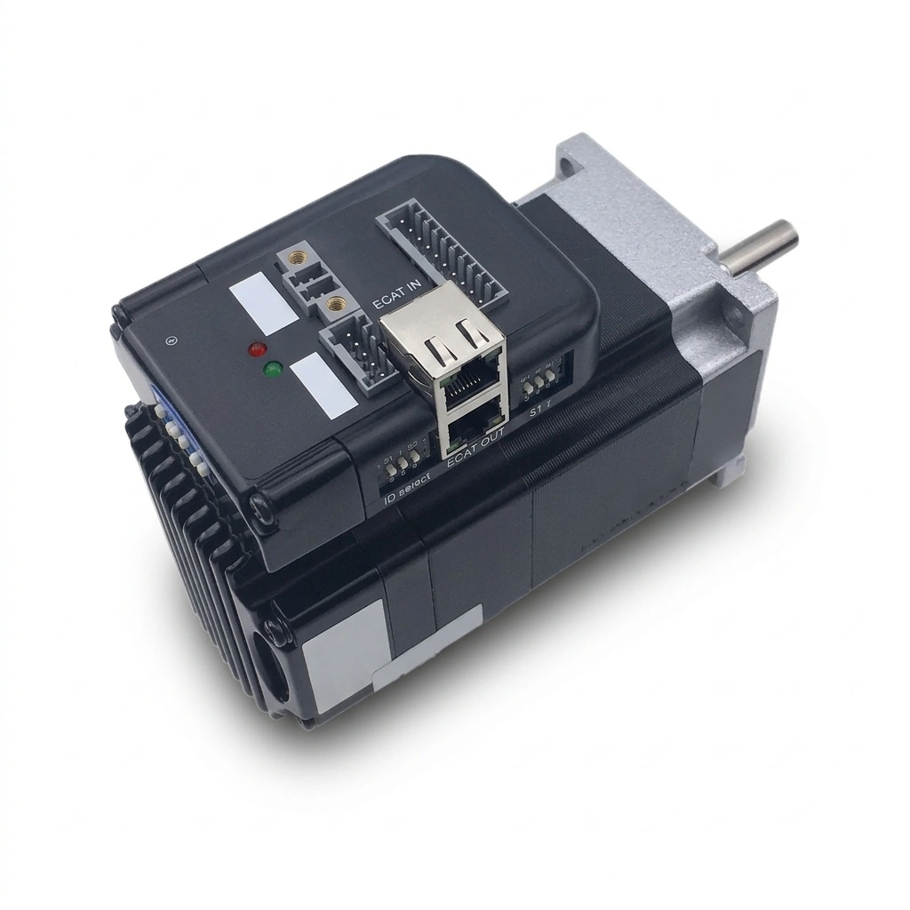
- Frame processing: An EtherCAT Slave Controller (ESC) reads outputs and inserts inputs as a frame passes. Conventional Ethernet switches normally forward by MAC address; this is different from EtherCAT's processing architecture.
- Distributed clocks: ETG describes device clock synchronization substantially below 1 µs. This is a clock property, not a guarantee of motor response, network cycle time, or final positioning accuracy.
- Cyclic Synchronous Position (CSP): The controller sends cyclic target positions, commonly through object
0x607A. Confirm the supported update interval, PDO layout, drive interpolation behavior, and master runtime before selecting a cycle target.
CANopen (CiA 301 & CiA 402)
CANopen combines a CAN network with application-layer services and device profiles. It can be economical when the controller already supports CANopen and the required drive modes fit the available bandwidth.
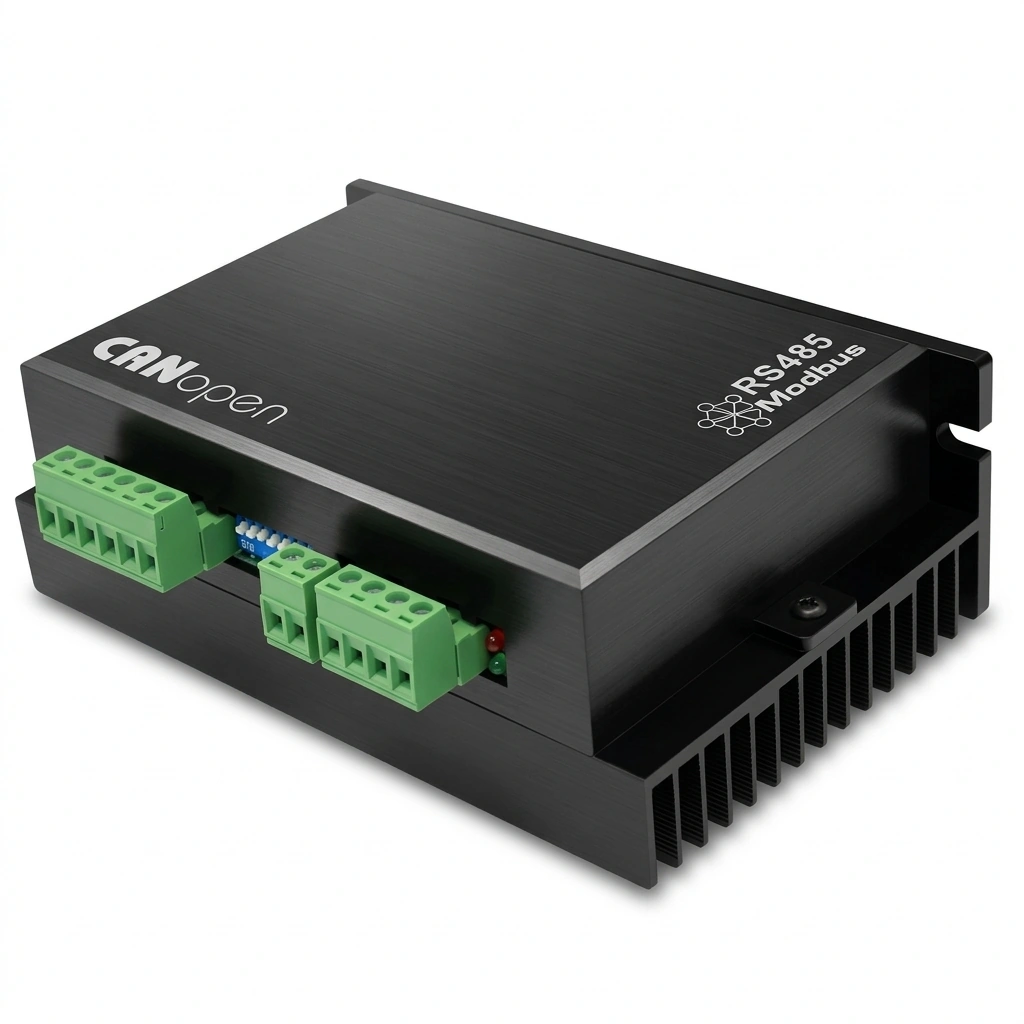
- Traffic budget: Classical CANopen uses node IDs 1–127; this is not a guarantee that 127 motion axes fit a chosen update cycle. CAN arbitration prioritizes messages rather than treating simultaneous transmissions as destructive collisions. Count command/status PDOs, SYNC, heartbeat, frame overhead, bit stuffing, and retries at the selected baud rate.
- Profile Position Mode (PPM): The master supplies the target and profile settings; the drive generates its local move. Ask whether the selected model supports PPM, interpolated position, CSP, or another required mode. CANopen does not inherently restrict every drive to PPM.
- Best fit: Independent point-to-point moves are a straightforward use case. Coordinated moves require verified synchronization, drive interpolation, and a controller/network timing budget.
Modbus RTU (Serial RS-485)
Modbus RTU commonly uses request/response polling on a half-duplex serial trunk. Its standard function codes access registers; the vendor defines motion registers and their behavior.
- Timing calculation: For an illustrative 8-byte request and 8-byte response with 11 bits per character, wire transmission alone is 16 × 11 / 19,200 = 9.17 ms at 19,200 baud. Add frame separation, device processing, adapter delays, and all other nodes to calculate the polling round. Use the Serial Line V1.02 timing rules for the selected baud rate.
- Synchronization boundary: Sequential register writes do not provide a standard coordinated-motion mechanism. A vendor may offer broadcast starts, buffered motion, or a hardware trigger, but these require documented behavior and application validation.
- Best fit: Conveyor speed settings, format adjustments, independent positioning, and dosing settings where the measured latency is acceptable.
For an initial shortlist, compare driver and controller options against your PLC's actual interfaces and supported modes.
4. Architectural Comparison: Discrete vs. Fieldbus Wiring
The diagram compares command/status connections for four axes. It shows an EtherCAT line, not a universal fieldbus wiring scheme; CANopen and RS-485 use different trunk/termination rules.
Reading the diagram: Pulse/direction uses separate axis signal connections; optional alarm and in-position signals can return status. EtherCAT links four network-capable drives in a line. Neither arrangement removes power or safety wiring. Ordinary EtherCAT does not carry motor supply power; combined power/data variants require explicitly compatible hardware.
5. The CiA 402 Standard: What Buyers and Software Teams Must Verify
When sourcing CANopen or EtherCAT CoE drives, the protocol name alone is insufficient. Specify the required CiA 402 modes, objects, and behavior. Parts of this profile are standardized in IEC 61800-7-201 and IEC 61800-7-301; neither the protocol label nor a generic conformity claim establishes application compatibility.
CiA 402 provides a common state machine and object model. It can reduce integration work, but optional functions, PDO mapping, units, scaling, homing, and firmware behavior still vary. A replacement supplier requires configuration review and machine acceptance testing; it is not automatically interchangeable.
Essential CiA 402 Objects to Verify in Device Files and Manuals
- Object
0x6040(Controlword): Used by the master PLC to command state transitions (Shutdown,Switch On,Enable Operation,Quick Stop,Fault Reset). - Object
0x6041(Statusword): Driven by the stepper driver to broadcast current status (Ready to Switch On,Switched On,Operation Enabled,Fault,Target Reached). - Object
0x6060(Modes of Operation): Configures the active control profile:- Value
1: Profile Position Mode (PPM) - Value
3: Profile Velocity Mode (PVM) - Value
6: Homing Mode - Value
8: Cyclic Synchronous Position (CSP) Mode - Value
9: Cyclic Synchronous Velocity (CSV) Mode
- Value
- Object
0x6061(Modes of Operation Display): Confirms the drive has transitioned into the requested mode. - Object
0x6064(Position Actual Value): Reports the drive's position value. Check whether it comes from an internal commanded-step accumulator or a physical encoder; an open-loop value cannot confirm that the shaft followed the command. See closed-loop stepper systems for feedback-based architectures.
Procurement check: CiA explicitly warns that optional functions and incomplete implementations limit interchangeability. A PPM-only drive cannot execute a CSP trajectory, even if it joins the network successfully. Request the EtherCAT ESI XML file (normally .xml) or CANopen EDS text file (.eds, INI-style) together with the firmware revision and supported-mode list. Import the file into the actual master tool and test the required modes before sample approval.
6. Panel-Mounted Discrete Drives vs. Integrated Fieldbus Stepper Motors
When standardizing on bus communication, machine builders face another major architectural decision: should the bus-type driver be mounted inside the central electrical cabinet, or integrated directly onto the rear of the NEMA stepper motor?
| Design parameter | Cabinet-mounted drive | Motor-integrated drive |
|---|---|---|
| Cabinet space | Requires mounting, cooling clearance, and terminals | Moves drive electronics onto the machine |
| Motor/encoder cables | Routed between cabinet drive and motor | Shorter or internal motor/encoder connections |
| Supply and network wiring | Cabinet power distribution plus network | Machine-side power distribution plus network |
| Thermal conditions | Check cabinet ambient and cooling | Check local ambient, motor heat, and derating |
| Vibration | Depends on panel installation | Electronics experience motor/machine vibration |
| Ingress protection | Verify drive and enclosure ratings | Verify complete assembly and mated connector ratings |
| Service replacement | Drive and motor may be replaced separately | Establish whether the drive module is separately replaceable |
Integrated Fieldbus Motors
An integrated unit combines a motor and drive; encoder feedback, connector type, and dual network ports depend on the model. Compare the motor envelope with hybrid stepper motor options, then request the actual integrated assembly drawing and datasheet.
- Where integration can help: Decentralized machinery with long cable routes or limited cabinet space. Shorter phase cables can reduce one EMI source, but do not eliminate shielding and bonding requirements.
- Environmental boundaries: Verify assembly ambient limits, duty-cycle derating, vibration qualification, and ingress rating. An enclosure rating or motor temperature limit alone does not qualify the integrated electronics for washdown or high-temperature service.
7. Operational Boundaries & Common Fieldbus Failure Modes
Deploying bus-controlled motion systems introduces failure modes that do not exist in traditional hardwired systems. Procurement and field service teams must account for these technical risks:
1. Shielding and bonding in high-EMI environments
Current-regulating drives switch motor phase currents and can disturb nearby signal wiring.
- Failure symptom: Communication errors or watchdog trips that correlate with acceleration or switching loads.
- Remediation: Follow the controller and drive EMC installation manuals for cable type, separation, shield bonding, and protective earth. Use industrial network-rated cable and the connector coding/pinout specified by both devices. An M12 shell alone establishes neither protocol compatibility nor an ingress rating.
2. Bus termination errors on CANopen and RS-485
- Failure symptom: Intermittent frames, faults on longer trunks, or unreliable downstream devices.
- Remediation: Terminate the two physical ends of a CAN trunk with the specified impedance, commonly 120 Ω. For RS-485, use termination matched to the cable and device installation guide, with polarization/biasing where required; do not add a terminator at every node. EtherCAT Ethernet links do not use external CAN/RS-485 termination resistors.
3. Cable disconnection and loss of communication
An EtherCAT line cable break can remove downstream devices; a CANopen or RS-485 wiring break has topology-dependent effects. Test every affected axis, including vertical or high-inertia loads.
- Remediation: Configure and test communication watchdogs and fault reactions. A drive may ramp down, coast, disable torque, or retain a previous command depending on firmware and settings. EtherCAT cable redundancy requires a supported master configuration and a return path; validate recovery on the actual system rather than assuming no cycle is lost. Ordinary fieldbus watchdogs do not provide a safety-rated stop or prevent a gravity-loaded axis from falling.
8. Sourcing & RFQ Checklist for Engineering Buyers
When issuing a Request for Quotation (RFQ) for bus-controlled stepper motor systems, use this three-phase verification framework to prevent integration surprises and protect production delivery schedules:
Phase 1: RFQ & Network Architecture Definition
- Protocol & Profile Specification: Have you specified EtherCAT CoE or CANopen with the required CiA 402 modes, or Modbus RTU with a documented vendor register map? CiA 402 is not a standard Modbus RTU requirement.
- Required Operational Modes: Does your master controller require Cyclic Synchronous Position (CSP) mode, or is Profile Position Mode (PPM) sufficient?
- Cycle Time Requirement: Have you stated your target communication cycle time (e.g., 500 µs for EtherCAT, 5 ms for CANopen) in the RFQ?
- Physical Connector Type: Have you specified the protocol-compatible connector, pinout, network cable, and complete mated-assembly ingress rating for the installation?
- DC Bus Operating Voltage: Have you checked the full supply range and calculated regenerative energy, maximum bus voltage, and any braking resistor/clamp requirement against the drive and supply manuals?
Phase 2: Technical File & Firmware Verification
- Device Description File Delivery: Has the supplier provided version-controlled EtherCAT ESI (
.xml) or CANopen EDS (.eds, text) files matching the sample firmware, or the Modbus register map, before prototype ordering? - Master Controller Compatibility: Have the sample drives been bench-tested on your exact PLC brand (e.g., Beckhoff TwinCAT 3, Siemens S7-1500 via gateway, Omron Sysmac, or Codesys V3.5)?
- Firmware Change Control: Does the supplier provide a formal Engineering Change Notice (ECN) agreement ensuring they will not modify drive firmware or internal ESC silicon without prior notification?
- Galvanic Isolation: Are communication isolation boundaries, working voltage, and test ratings documented and suitable for the machine's grounding and electrical design?
- Safety Integration: Has the machine safety assessment defined the required stop function, STO capability, brakes, isolation, and any contactors? Verify model-specific certification and the complete safety circuit; STO removes torque and does not itself brake, hold a vertical load, or provide electrical isolation.
Phase 3: Incoming Quality Control (IQC) & Batch Acceptance
- Node Address Verification: Is the model's documented address/identity method tested, including replacement behavior? Physical rotary switches are not universal.
- Conformance Evidence: For EtherCAT, is there relevant CTT evidence for the delivered model/firmware and an explanation of unresolved findings? For CANopen or Modbus, request protocol-appropriate evidence plus application tests.
- Thermal & Fault Acceptance: Have you agreed on a representative load, ambient, duty cycle, duration, allowable temperature/error limits, and recorded results? Include power-cycle, cable-loss, homing, and recovery tests on the actual PLC.
- Harness Durability: Are cable bend radius, movement profile, connector retention, and documented flex-life conditions suitable for the machine? A cycle count without its test conditions is insufficient.
9. Frequently Asked Questions (FAQ) for Engineering Buyers
When is EtherCAT truly justified over CANopen for NEMA stepper motors?
Shortlist EtherCAT when the required coordinated trajectory, axis count, and controller architecture favor its cyclic update and clock synchronization capabilities. Shortlist CANopen when the supported drive modes and calculated traffic budget meet the application. There is no universal two-millisecond or six-axis cutoff; compare complete system quotes and verify trajectory error under load.
Can CANopen stepper drives perform circular interpolation?
Yes, with appropriate controller/drive modes, synchronization, interpolation, and sufficient bandwidth. CANopen has no universal 5–10 ms minimum cycle. Calculate the payload/frame budget for all axes, then test contour error at the required speed and acceleration. EtherCAT is often easier to scale for short-cycle coordinated motion, but the protocol alone does not guarantee smoothness or accuracy.
How do we prevent high PWM switching noise from corrupting fieldbus communication?
Follow the drive and controller EMC manuals for separation, shielding, and equipotential bonding; the required cable and grounding arrangement depend on the installation. Use the correct Ethernet, CAN, or RS-485 cable for the selected protocol. Check error counters during worst-case switching and movement; no universal cable spacing or shield construction guarantees immunity.
What is the practical difference between CiA 402 CSP mode and Profile Position Mode (PPM)?
In PPM, the master sets the target and profile parameters, and the drive generates a local trajectory. In CSP, the controller supplies cyclic target positions at the agreed update interval; the drive may still interpolate or filter internally. Coordinated gearing, camming, or contouring also depends on the master's motion functions, drive mode support, and tested timing.
Can open-source or PC-based controllers communicate with these drives?
Yes, if the controller provides a compatible protocol stack, physical interface, device configuration, and timing behavior. A PC Ethernet port alone is not an EtherCAT motion master, and a CAN adapter alone does not implement CANopen drive control. Request a demonstrated configuration for your operating system and runtime, and validate cycle timing under load.
What happens if an RJ45 fieldbus cable is unplugged while the machine is running?
The affected drives may lose cyclic commands and trigger configured communication timeouts. Their response is model- and configuration-dependent: deceleration, coasting, torque removal, or other behavior may result. Test timeout, stopping distance, and recovery for every affected axis. Neither CiA 402 nor an ordinary network watchdog guarantees collision prevention or a safety-rated stop.
10. Partnering with a Fieldbus Motion Specialist
Transitioning your machine design from legacy discrete wiring to modern EtherCAT or CANopen bus control requires more than purchasing off-the-shelf components. It demands verified device description files, robust firmware support, and component traceability across multi-year production runs.
For an RFQ to NEMA Stepper Motors, include the PLC/runtime version, protocol, required modes, axis count, cycle target, load/speed profile, supply range, environmental limits, and quantity plan. Ask for model-specific confirmation of:
- ESI XML or EDS text files matching the offered firmware, or the Modbus register map.
- Connector pinout, complete assembly ingress rating, and cable requirements.
- Motor/drive compatibility, torque-speed data, thermal limits, and customization feasibility.
- Sample availability, master compatibility evidence, support scope, and firmware change control.
To evaluate prototype samples, review fieldbus communication files, or discuss your machine motion architecture, explore our stepper drivers and controllers or contact our motion engineering team directly.
Accelerate Your Fieldbus Motion Integration
Send your PLC, axis count, cycle target, and load profile. Request a model-specific quote, sample availability, and matching device files before approving a prototype.
Request a Quote & Engineering Consultation
Sources / References
- EtherCAT Technology Group — EtherCAT technology overview: Frame processing, distributed clocks, ESI XML descriptions, redundancy, and conformance testing. Clock synchronization figures do not establish the performance of a particular motor/drive system.
- CAN in Automation — CiA 402 series: CANopen device profile for drives and motion control: Drive state machine, modes, related IEC profile standards, and limits to interchangeability.
- Modbus Organization — Specifications and implementation guides: Official index for Application Protocol V1.1b3 and Serial Line Protocol and Implementation Guide V1.02. Use the current linked documents and the supplier's motion register map; the older legacy serial specification is identified separately on that page.
Evidence boundary: These official sources explain protocol behavior; they do not substantiate supplier prices, product certifications, or measured labor savings. The cost and serial-transmission calculations in this guide are illustrative and reproducible, not hardware test results. Verify the delivered model and document revisions at ordering.
Author

Categories
More Posts
Stepper Motor Driver Selection: DM542 vs DM556 vs DM860
A buyer-focused comparison of the three most popular DSP stepper drivers with real specification data, motor matching rules, and thermal management guidance for industrial OEM projects.
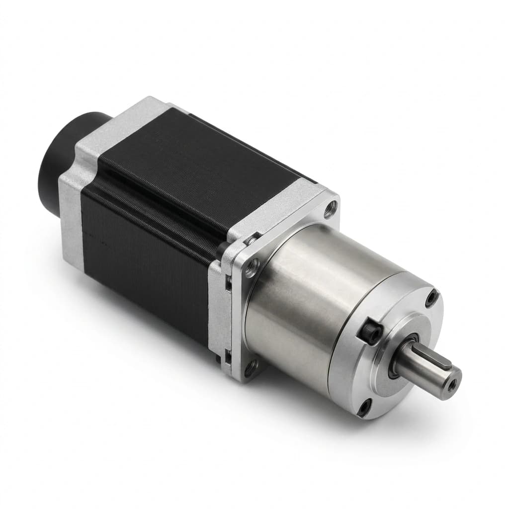
Geared NEMA Stepper Motors: Planetary vs. Spur Gearbox Selection for OEMs
Compare planetary and spur gearboxes for NEMA stepper motors. Learn how to evaluate torque multiplication, backlash, and BOM costs for 2026 OEM automation projects.
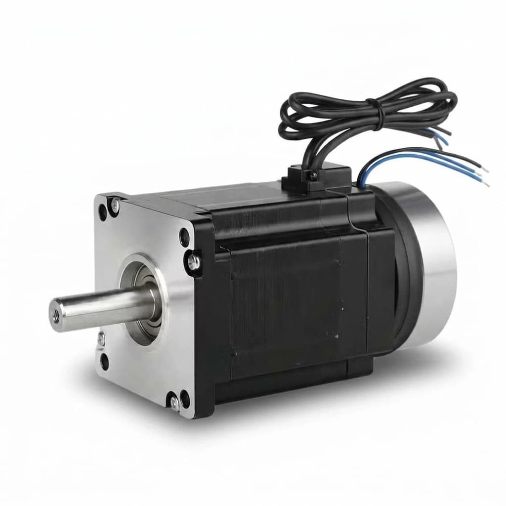
NEMA Stepper Motor with Electromagnetic Brake: 2026 Z-Axis Sourcing & Sizing Guide
A comprehensive OEM guide for specifying NEMA stepper motors with power-off electromagnetic brakes for vertical Z-axis applications. Covers sizing, holding vs dynamic torque, 24V interlock wiring, and procurement checklists.