
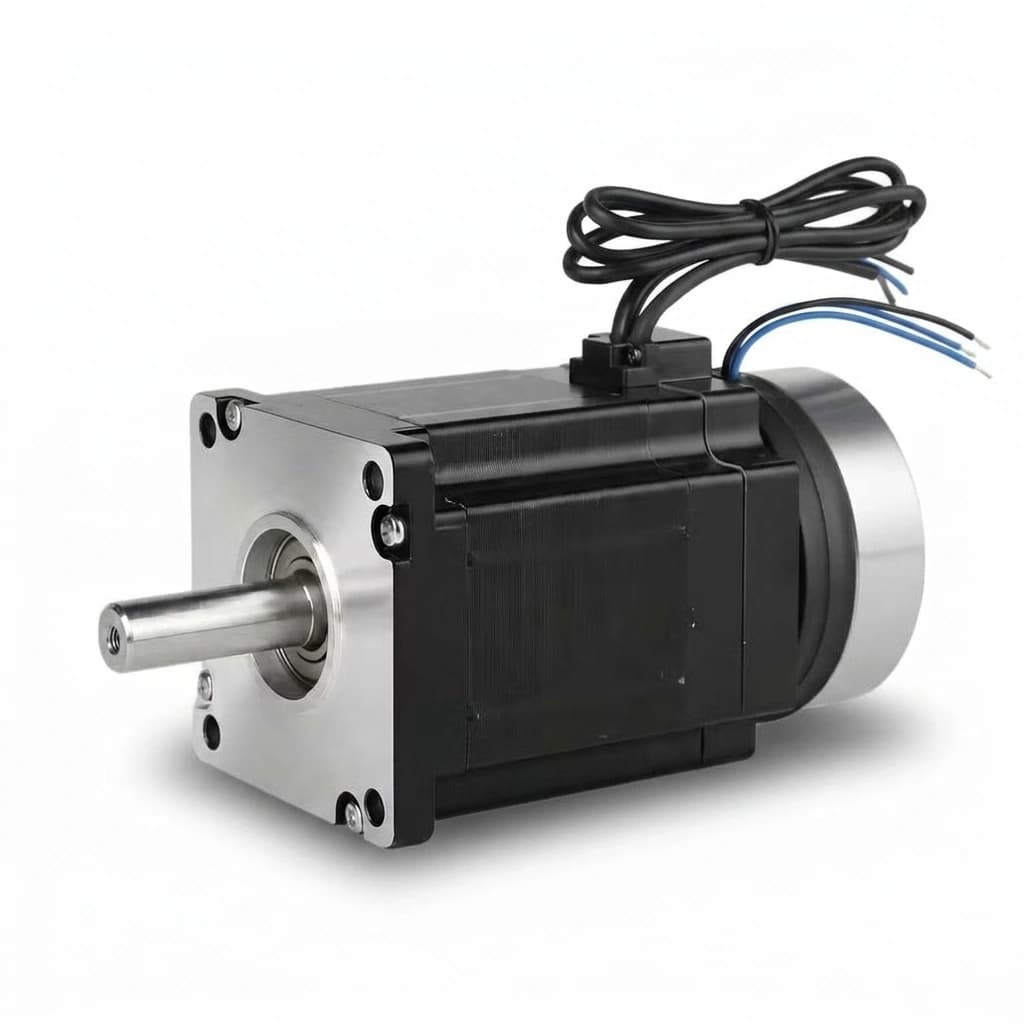
NEMA Stepper Motor with Electromagnetic Brake: 2026 Z-Axis Sourcing & Sizing Guide
A comprehensive OEM guide for specifying NEMA stepper motors with power-off electromagnetic brakes for vertical Z-axis applications. Covers sizing, holding vs dynamic torque, 24V interlock wiring, and procurement checklists.
"Why did the spindle crash into the worktable the moment we hit the emergency stop?"
For engineers designing vertical axes—such as 3D printer Z-axes, CNC router spindles, pick-and-place heads, and automated dispensing nozzles—gravity is the ultimate enemy of power-off states. When power is removed from a standard hybrid stepper motor, the holding torque drops to zero. If the lead screw or ball screw is not self-locking, the payload will back-drive the screw and crash into the machine bed.
The industry-standard solution in 2026 for NEMA 17, NEMA 23, and NEMA 34 systems is the power-off electromagnetic brake. Also known as a fail-safe brake, this device mounts to the rear shaft of the stepper motor and mechanically locks the rotor whenever power is lost.
This guide provides a comprehensive framework for procurement teams and OEM engineers to source, size, and implement NEMA stepper motors with electromagnetic brakes, avoiding common pitfalls related to brake thermal overload, engagement delays, and improper wiring.
Scope and limits, reviewed July 24, 2026: This guide is for global OEM procurement and engineering teams specifying NEMA 17, NEMA 23, or NEMA 34 stepper motors for vertical Z-axis loads. Treat the torque, heat, and delay ranges below as first-pass screening values; final brake torque, enclosure rating, E-stop behavior, and compliance path must be validated against your payload, screw efficiency, duty cycle, local machinery safety rules, and supplier datasheet.
The Physics of Vertical Axes
When sizing a motor for a horizontal axis, the primary calculation involves overcoming inertia during acceleration and overcoming friction during continuous motion. When the motor stops, the friction of the linear guides and the screw is usually enough to keep the load in place, even if the motor loses power.
Vertical axes change the equation entirely. Gravity exerts a continuous downward force equal to Mass × 9.81 m/s². To maintain position, the system must provide a counter-force.
When a stepper motor is powered, its holding torque keeps the rotor locked in place. However, the moment an emergency stop (E-Stop) is pressed, or a facility power outage occurs, the motor coils de-energize.
If the linear transmission is a high-efficiency ball screw (often 90% efficiency), the downward force of gravity will back-drive the screw nut, spinning the motor shaft backward and sending the payload crashing down. While trapezoidal lead screws (Acme screws) have lower efficiency and can sometimes self-lock, vibrations or heavy payloads can still cause them to creep downwards over time.
The electromagnetic brake solves this by applying a mechanical friction plate to the rear shaft of the motor the instant the 24V DC signal is cut off.
Holding Brakes vs. Dynamic Stopping Brakes
The most critical mistake an OEM can make when sourcing a NEMA stepper motor with a brake is confusing a static holding brake with a dynamic stopping brake.
Static Holding Brake (Fail-Safe Parking)
The vast majority of brakes mounted to NEMA 17, NEMA 23, and NEMA 34 stepper motors are static holding brakes.
- Operation: They are designed to engage after the motor has brought the load to a complete halt.
- Wear: Because the shaft is already stationary when the friction plate clamps down, there is virtually zero wear on the brake pad. They can last for millions of cycles.
- Safety: If power is suddenly lost while moving, the brake will slam shut to stop the load, acting as an emergency brake. However, doing this repeatedly will glaze the friction material, drastically reducing its holding torque and eventually leading to brake failure.
Dynamic Stopping Brake
A dynamic brake is designed to actively scrub off kinetic energy while the shaft is spinning. These are much larger, heavily ventilated, and use different friction materials. You will rarely find true dynamic brakes integrated into standard NEMA footprint hybrid steppers; they are typically standalone components on large AC servos or induction motors.
OEM Takeaway: Your machine's control logic must be programmed to decelerate the stepper motor to zero speed before cutting power to the brake relay. The brake should only be used as a parking brake or an absolute last-resort emergency stop.
Sourcing Options for Z-Axis Load Management
When designing a vertical axis, OEMs have a few mechanical options. Here is how they compare in the context of 2026 industrial supply chains.
| Load Management Method | BOM Cost Impact | Sourcing Complexity | Z-Axis Suitability | Failure Mode at Power Loss |
|---|---|---|---|---|
| No Brake + Ball Screw | Lowest | Very Low | Unsuitable | Immediate payload crash. |
| No Brake + Acme Lead Screw | Low | Low | Marginal | May self-lock, but prone to creeping under vibration. |
| Gas Spring / Counterweight | Medium to High | High (Bulky) | Good for reducing motor size | Payload remains suspended, but adds significant mass/volume. |
| EM Brake Stepper Motor | Medium | Low (Standard NEMA) | Excellent (Industry Standard) | Brake engages, payload is securely locked in place. |
| External Pneumatic Brake | High | High (Needs air supply) | Heavy Industrial | Safe, but requires complex air plumbing and solenoid valves. |
| Closed-Loop Motor (No Brake) | Medium | Low | Unsuitable | Drops load when power fails; closed-loop logic turns off. |
For many packaging, dispensing, and CNC Z-axis applications where the payload falls within standard NEMA brake torque ranges, the integrated Electromagnetic (EM) Brake Stepper Motor provides a practical balance of cost, footprint, and fail-safe behavior.
Sizing the Brake and the Motor
Properly sizing a brake motor requires looking at both the motor torque and the brake torque independently.
1. Motor Torque Sizing
The stepper motor must be able to lift the payload against gravity and accelerate it.
Calculate the torque required to lift the mass (T_gravity), plus the torque required to accelerate the inertia (T_accel). Add a 30-50% safety margin because stepper motors lose torque at higher RPMs.
2. Brake Torque Sizing
The electromagnetic brake does not need to overcome acceleration inertia; it only needs to hold the static mass against gravity. Most standard NEMA brake motors come with a brake torque roughly equal to or slightly less than the motor's holding torque.
- NEMA 17 Brake: Typically 0.25 Nm to 0.4 Nm holding torque.
- NEMA 23 Brake: Typically 1.5 Nm to 2.5 Nm holding torque.
- NEMA 34 Brake: Typically 4.0 Nm to 8.0 Nm holding torque.
If your payload requires 1.0 Nm just to hold against gravity, a NEMA 23 motor with a 2.0 Nm brake is perfectly adequate. Do not over-specify the brake torque excessively; higher torque brakes require larger electromagnetic coils, which consume more power and generate more waste heat.
Thermal Management and Heat Considerations
This is the hidden trap of brake motors. A power-off electromagnetic brake requires continuous electrical power (usually 24V DC) to stay disengaged so the motor can spin.
A typical NEMA 23 brake consumes around 5 to 10 Watts of power constantly while the machine is running. This power is entirely converted into heat at the rear of the motor. Because stepper motors already run hot (often 60°C to 80°C surface temperature), the added heat from the brake coil can push the rear bearing past its thermal limit if the machine is poorly ventilated.
Mitigation strategies:
- Reduce motor standby current: Ensure your stepper drive is configured to drop motor current by 50% when idle.
- Ventilation: Do not enclose a brake stepper in a completely sealed, unventilated box without heatsinking the front flange to a large metal chassis.
- Brake Voltage Control (Advanced): Some high-end machines use an over-excitation circuit. They hit the brake with 24V to quickly pull the spring back, then drop the voltage to 12V (PWM) to hold it open, drastically reducing heat generation.
The 24V Relay Interlock: Wiring Best Practices
The brake consists of two non-polarized wires (usually red/blue or black/black). Applying 24V DC releases the brake. Removing 24V DC engages the brake.
Never wire the brake directly to the stepper driver's motor output phases. Never wire the brake directly to the main system power switch without a relay interlock.
The correct OEM implementation uses a relay controlled by the stepper driver's FAULT or ALARM output, combined with the machine controller's ENABLE signal.
- Power Supply: Provide a dedicated 24V DC power supply for the brake. Sharing the logic power supply can cause voltage dips when the brake coil switches, causing microcontrollers to reboot.
- Flyback Diode: The brake is a massive inductor. When the relay opens, the magnetic field collapses, generating a high-voltage spike (flyback). You must install a flyback diode (e.g., 1N4007) in reverse parallel across the brake wires. If you skip this, the voltage spike will destroy the control relay or the driver board in a matter of days.
- Engagement Delay: Electromagnetic brakes take time to physically move—often 20 to 50 milliseconds. The machine controller must wait 50ms after turning on the brake power before sending step pulses, otherwise the motor will try to turn against a locked brake, resulting in instant position loss.
Driver Selection for Brake Steppers
Not all stepper drivers are optimized for vertical axes with mechanical brakes. When sourcing drivers, OEMs should look for the following features:
- Programmable Alarm Outputs: The driver must have a configurable digital output that asserts when the drive faults (e.g., overcurrent, overvoltage, or step-loss in a closed-loop system). This output must be fast enough to drop the brake relay before the payload falls significantly.
- Adjustable Idle Current: As discussed in the thermal section, reducing the idle current is critical when a brake is heating the motor from the rear. Look for drives that allow 40%, 50%, or 60% holding current reduction when pulses are not received for 0.5 seconds.
- Over-voltage Protection Thresholds: When a heavy payload decelerates rapidly on a vertical axis, the motor acts as a generator, pumping energy back into the drive (back-EMF). In high-speed Z-axis applications, this regenerated energy can trip the drive's overvoltage alarm. Sourcing drives with high maximum voltage ratings or adding an external braking resistor module is highly recommended for payloads exceeding 10 kg.
Environmental Factors and Ingress Protection (IP Ratings)
A standard NEMA 23 stepper motor might be rated IP40 or IP54. However, the addition of an electromagnetic brake often lowers the overall IP rating of the assembly if the brake housing is exposed.
- Dust and Particulates: In CNC routing or 3D printing, fine dust can enter the gap between the brake friction plate and the electromagnet. Over time, this dust prevents the brake from fully engaging, reducing its holding torque. If your machine operates in a dusty environment, you must source a fully enclosed brake motor, often requiring an IP65 rating on the complete assembly.
- Oil and Moisture: Oil is fatal to friction brakes. If cutting fluid or lubrication oil drips into the brake assembly, the friction coefficient drops to near zero. A brake rated for 2.0 Nm might only hold 0.1 Nm when soaked in oil. For milling machines, the brake must be sealed with O-rings, and the motor must feature a rear shaft seal.
- Vibration: Heavy vibration can cause the brake's retaining springs to fatigue or vibrate harmonically. Ensure the supplier uses high-cycle springs designed for continuous industrial vibration.
Sourcing Considerations for Global Supply Chains
For global OEMs and procurement teams building hundreds of machines annually, supply chain stability for brake motors is more complex than standard steppers.
- Matched Sets vs. Retrofits: It is technically possible to buy a standard double-shaft stepper motor and bolt an aftermarket brake to the rear shaft. However, for production machines, OEMs should always source pre-assembled, factory-tested brake motors. The factory will ensure the rotor gap is perfectly shimmed and the friction plate is aligned. Misaligned aftermarket brakes will rub constantly, causing excess heat and premature failure.
- Lead Times: While standard NEMA 23 motors are commodities with short lead times, specific brake motor configurations (e.g., NEMA 23, 2.0 Nm motor, 24V 2.0 Nm brake, 1000-line encoder, IP65 sealed) are often built-to-order. Procurement teams should buffer lead times by 2-4 weeks compared to standard motors.
- Customization Options: Many top-tier suppliers offer customization for the brake wires, such as integrating them into the main motor power cable with a 6-pin connector, saving assembly time on the factory floor.
OEM Sourcing Checklist for Brake Steppers
Before finalizing a BOM for a vertical axis machine, review this engineering checklist:
- Flyback Diode Included: Is the suppression diode wired across the brake coil or at the relay output?
- Delay Timers Programmed: Does the PLC/Controller wait at least 50ms after sending the Enable signal before generating motion pulses?
- Drop Delay Programmed: When parking the axis normally, does the controller wait 50ms for the motor to stop before de-energizing the brake?
- Current Reduction: Is the driver's auto-standby current reduction enabled to offset the extra heat from the brake coil?
- Dedicated Power: Is the brake running on a power supply separate from sensitive 5V/3.3V logic components?
- E-Stop Interlock: Does the physical Emergency Stop button hardware-cut the 24V line to the brake relay, ensuring an absolute fail-safe drop?
- Connector Spec: Are you specifying secure, locking connectors (like aviation plugs or Molex Minifit) for the brake wires, since a disconnected wire means the machine axis freezes?
- Environmental Rating: Does the brake enclosure match the IP rating required by the machine's operating environment (e.g., IP65 for oil/water exposure)?
Frequently Asked Questions (FAQ)
1. Can I use a 12V supply on a 24V brake?
No. The electromagnetic coil will not generate enough magnetic flux to overcome the internal springs. The friction plate will drag against the rotor, destroying the brake and stalling the stepper motor. Always use the rated voltage.
2. Can I manually release the brake if the power goes out?
Standard NEMA stepper brakes do not have manual release levers (unlike large hoist motors). If power is out and you need to move the Z-axis, you must supply 24V to the brake wires from a battery or temporary power source, or mechanically uncouple the motor shaft from the screw.
3. Does the brake reduce the motor's usable torque?
When fully disengaged (powered), the brake has zero contact with the rotor. It does not reduce the running torque. However, the added mass on the rear shaft slightly increases the rotor inertia, which can minutely affect peak acceleration.
4. What happens if the brake wires short circuit?
If the wires short, the 24V supply will trip its overcurrent protection. Because voltage to the coil drops to zero, the springs will engage the brake, locking the axis. This is the intended fail-safe behavior.
5. Can a closed-loop stepper motor eliminate the need for a brake?
No. A closed-loop stepper motor (stepper servo) corrects position errors while power is applied. If main power is cut, the closed-loop driver goes dark, and gravity will still back-drive the screw. Vertical closed-loop axes still absolutely require mechanical brakes.
6. Are 12V brakes available for NEMA 17 sizes?
Yes. While 24V is the industrial standard, many manufacturers offer 12V brake coils specifically for NEMA 17 frame sizes, which are popular in desktop 3D printers and light laboratory automation where the main system bus is 12V.
Sources and References
- Oriental Motor: Stepper Motor Frame Sizes and Electromagnetic Brake Options - Technical specifications on holding torque integration. orientalmotor.com
- Texas Instruments: Closed Loop Stepper Motor Design With Encoder for Stall Detection - Handling driver faults and relay logic for motor safety. ti.com
- ISO 12100: Safety of machinery - General principles for design - Risk assessment and risk reduction - Standards regarding gravity-loaded vertical axes and fail-safe mechanical locking requirements. iso.org
Next Steps for Your Project
Sizing a vertical axis requires careful balancing of holding torque, brake torque, and thermal limits. Choosing the wrong brake configuration can lead to dropped payloads, glazed friction plates, or blown driver boards.
Whether you are designing a medical dispensing robot or a heavy-duty CNC Z-axis, our engineering team can help you select the exact NEMA 17, NEMA 23, or NEMA 34 brake motor for your payload.
Review our standard catalog of NEMA Stepper Motors and Stepper Drivers, or send your vertical payload weight, screw pitch, and speed requirements directly to [email protected] for a free sizing calculation and OEM quote.
Author

Categories
More Posts
CE, RoHS, and UL Compliance for NEMA Stepper Motors in 2026
Source compliant NEMA stepper motors in 2026 with CE, RoHS, UL, and REACH checks, supplier RFQ questions, and document evidence before quote.
IP65 vs IP67 Waterproof Stepper Motors: OEM Selection Guide
How to specify waterproof NEMA stepper motors for harsh environments without overpaying. Covers shaft seals, thermal derating, and cable traps.
NEMA Stepper Motor Industry Update (April-May 2026): Tariff Mechanics, Standards Activity, and Buyer Decisions
April-May 2026 NEMA stepper update for OEM teams: U.S. tariff shifts, NEMA standards activity, frame-size and driver-current tradeoffs, and PO-release controls.