
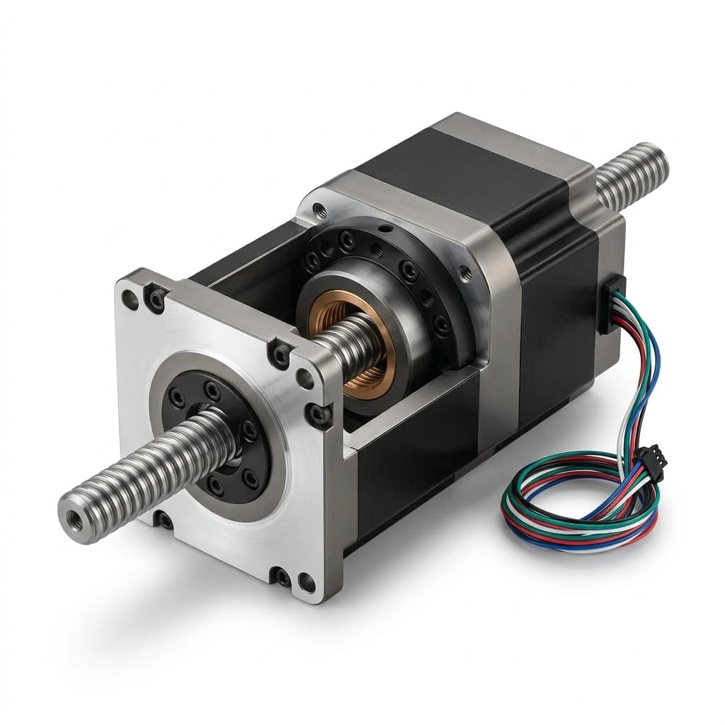
Linear Stepper Actuators: Captive, Non-Captive, and External Lead Screw OEM Sourcing Guide
Compare captive, non-captive, and external linear stepper actuators. Check thrust, screw lead, backlash, and vertical-load risks, then prepare your OEM RFQ.
Selection Summary
- Direct-drive linear stepper actuators combine a stepper motor with a screw-and-nut transmission, reducing separate coupling hardware. Captive and non-captive types rotate an internal nut; external types rotate the screw.
- Captive actuators: Select for short strokes where an external anti-rotation mechanism is difficult to package. The internal spline restrains output rotation; confirm the supplier's rated stroke and load limits.
- Non-captive actuators: Select when extended stroke length is needed inside a minimal footprint. The lead screw travels completely through a hollow rotor, but your external carriage or linear rail must provide the anti-rotation guide.
- External (motorized lead screw) actuators: Select when a rotating screw and external traveling nut suit your guided carriage. Check bearing support, critical speed, and buckling over the full stroke.
- Critical engineering boundaries: Carry side loads and moments through suitable guides. Treat vertical load retention as a separate design requirement: screw lead or nominal efficiency alone cannot establish safe power-off holding.
In automated equipment design, converting rotary stepper motor motion into precise linear displacement is one of the most common mechanical challenges. Historically, machine builders relied on a discrete assembly: a standard rotary NEMA stepper motor, an aluminum flexible spider or bellows coupling, external angular contact bearing blocks, a machined lead screw or ball screw, and a fabricated mounting bracket.
While functional, discrete assemblies introduce significant liabilities for original equipment manufacturers (OEMs):
- Alignment work: The motor shaft, coupling, and screw supports must share the intended axis. Misalignment can increase friction and bearing loads.
- Packaging: Couplings and bearing blocks consume space beyond the useful stroke. Compare complete assembly drawings rather than motor body lengths alone.
- BOM coordination: Motor, coupling, support bearings, screw, and nut interfaces must be controlled, whether sourced from one vendor or several.
Integrated linear stepper actuators reduce some of this interface work. Internal rotating-nut designs and external rotating-screw designs still require different mounting, clearance, and load-support arrangements.
This guide compares Captive, Non-Captive, and External configurations, explains preliminary thrust and speed calculations, and turns the remaining engineering questions into an OEM RFQ checklist.
Published and reviewed: 2026-10-29. Scope: Global OEM engineering and procurement screening for NEMA 8, 11, 14, 17, and 23 hybrid linear stepper actuators. NEMA frame size describes a mounting envelope, not a thrust or accuracy rating. This is a literature-based selection guide with a hypothetical sizing example, not a hardware test report. Final stroke, life, thermal limits, cleanroom or medical suitability, and power-off behavior require the selected assembly's datasheet and application validation.
Need application assistance or a customized prototype? Send your stroke, payload mass, target velocity, and mounting orientation for an engineering review.
1. Architectural Deep-Dive: Captive vs. Non-Captive vs. External
Start with which part moves and how it is restrained. These distinctions follow Haydon Kerk's actuator architecture guide.
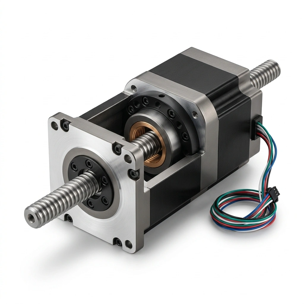
Architecture Comparison Diagram
The functional difference lies in which component rotates, which component translates, and where the anti-rotation restraint is physically housed:
1. Captive Linear Stepper Actuators
- Mechanism: A rotating internal nut drives a translating shaft; a spline or equivalent feature inside the front sleeve prevents output rotation.
- Engineering advantage: Built-in anti-rotation can simplify a short-stroke mechanism.
- Selection boundary: Confirm the model's usable stroke, retracted envelope, and permitted output loads. An internal spline is not a substitute for a payload guide capable of carrying side loads and moments.
2. Non-Captive Linear Stepper Actuators
- Mechanism: A screw passes through the rotating rotor nut. With the motor fixed, an external restraint prevents screw rotation so the screw translates.
- Engineering advantage: Through-travel can reduce motor-side packaging. Alternatively, fix the screw and let a guided motor carriage travel along it; wiring must then move with the motor.
- Selection boundary: Reserve clearance for the entire screw travel. Check unsupported length, buckling under compression, alignment, and the supplier's thrust rating rather than assuming unlimited stroke.
3. External (Motorized Lead Screw) Actuators
- Mechanism: The rotor rotates a screw while an external nut attached to a guided carriage translates.
- Engineering advantage: The motor can sit at the end of a conventional rail stage, with the nut carrying the axial drive interface.
- Selection boundary: Long rotating screws need critical-speed and support checks. Agree the end-bearing arrangement with the actuator supplier; adding a second axial locating bearing without accounting for alignment and thermal expansion can overconstrain the assembly.
2. Multi-Architecture Engineering & Sourcing Decision Matrix
Use this matrix to compare complete assemblies. Stroke, price, assembly time, and accuracy are supplier- and application-specific; the matrix does not claim measured cost or performance advantages.
| Architectural Parameter | Captive Actuator | Non-Captive Actuator | External Actuator | Discrete Rotary + Coupler Stage |
|---|---|---|---|---|
| Stroke constraint | Limited by captive sleeve and rated travel | Screw length, clearance, and compression stability | Screw span, support, and critical speed | Selected screw and support system |
| Anti-rotation | Internal spline or equivalent | External restraint on screw; guide a moving motor if screw is fixed | External guide restrains traveling nut | External guide restrains traveling nut |
| Side and moment loads | Payload guide required unless explicitly rated | Carry through external guides | Carry through rail and carriage | Carry through selected stage guides |
| Packaging check | Extended and retracted sleeve envelope | Clearance at both screw ends | Motor plus rotating screw span | Motor, coupling, screw, and supports |
| Alignment work | Mounting face and payload interface | Motor axis versus screw restraint | Motor, nut, rail, and end support | Coupling alignment plus screw, nut, and supports |
| End support | Follow captive output design | Do not fix a translating screw in a stationary bearing | Optional engineered support arrangement | Designed fixed/floating bearing arrangement |
| Backlash control | Confirm available nut/preload options | Confirm rotor-nut preload and drag | Select external nut and preload | Select lead-screw or ball-screw assembly |
| Cost comparison | Quote complete actuator and guide | Include external restraint and moving clearances | Include nut, rail, guards, and supports | Include coupling, bearings, machining, and assembly |
| Candidate application | Short-stroke valve or pump mechanism | Compact dispenser or guided translating screw | Guided optical or printer stage | Axis needing separately selected motor and transmission |
3. Mathematical First-Principles: Thrust, Speed, and Efficiency
Size at the operating speed. Holding torque is a stationary rating and cannot establish available thrust during a move.
Core Thrust and Speed Equations
For preliminary steady-motion screening:
F = 2 × π × T × η / L
T_load = F_required × L / (2 × π × η)
rpm = 60 × v / lead
T_required = T_load + T_rotational_acceleration + T_drag + T_other_lossesFis axial force in N;Tis usable screw-driving torque in N·m after other torque demands.Lis screw lead in m/revolution in the force and torque equations. Lead is travel per revolution; it differs from pitch on a multi-start thread.ηis screw/nut efficiency as a fraction, using the selected supplier's conditions. Include preload drag separately only if the quoted efficiency or thrust curve does not already include it.- For rpm, use the same length unit for
v(length/second) andlead(length/revolution). F_requiredincludes axial process load, gravity along the axis, guide friction, and linear acceleration. The rotational acceleration term covers rotor and rotating transmission inertia.
Compare the total requirement with the motor's dynamic torque-speed curve at the specified driver voltage, phase-current setting, and drive mode, then check actuator thrust and bearing limits. A calculated force above the mechanical rating does not increase the actuator's usable capacity.
Worked RFQ Example — Hypothetical, Not Measured
Assume a vertical axis has an already calculated peak axial demand of 100 N, including gravity and linear acceleration, a 2 mm/rev lead, and 20 mm/s target speed. For illustration only, assume 40% screw efficiency, 0.01 N·m preload drag, and 0.01 N·m rotational acceleration torque:
Speed = 60 × 20 / 2 = 600 rpm
Load torque = 100 × 0.002 / (2 × π × 0.40) = 0.0796 N·m
Total before margin = 0.0796 + 0.01 + 0.01 = 0.0996 N·m
Illustrative 1.5× margin target = 0.1494 N·m at 600 rpm
This establishes an RFQ screening target of approximately 0.15 N·m at 600 rpm, not a NEMA frame recommendation or proof of satisfactory operation. Replace every assumed loss and margin with supplier data and your motion profile; verify thermal duty, buckling, and power-off retention separately. Do not apply this example's efficiency to another nut or coating.
Lead Screw Efficiency and Power-Off Holding
Sliding screw efficiency depends on lead angle, thread geometry, nut material, coating, lubrication, and operating conditions. Thomson's lead-screw application guidance explains why higher leads can improve speed and efficiency while making backdriving more likely.
The often-used 50% efficiency boundary is a screening rule, not a guarantee that a lower-efficiency assembly will safely retain a vertical load. Static friction, wear, vibration, and lubrication can change behavior. Obtain the selected assembly's backdrive data and assess the complete machine's loss-of-power behavior. Where gravity can cause hazardous motion, specify a suitable retention system, such as a power-off brake for a vertical stepper axis. A holding-only brake must not be treated as a rated dynamic stopping brake.
4. Screw Lead vs. Speed: Calculated Sourcing Reference
The following candidate leads are arithmetic examples, not standard thread designations or available product specifications. Calculations assume a 1.8° motor with 200 full steps per revolution: travel per full step = lead / 200. Full-step travel is a command increment, not positioning accuracy; microstepping does not remove backlash or lead error.
| Candidate Lead | Travel per Full Step | rpm at 20 mm/s | rpm at 50 mm/s | OEM Sizing Focus |
|---|---|---|---|---|
| 0.5 mm/rev | 0.0025 mm (2.5 µm) | 2400 | 6000 | Fine command increment; check torque at the required high rpm |
| 1 mm/rev | 0.005 mm (5 µm) | 1200 | 3000 | Compare speed demand with dynamic thrust curve |
| 2 mm/rev | 0.01 mm (10 µm) | 600 | 1500 | Check torque, drag, and thermal duty together |
| 4 mm/rev | 0.02 mm (20 µm) | 300 | 750 | Lower rpm at a given speed; higher load torque at equal efficiency |
| 8 mm/rev | 0.04 mm (40 µm) | 150 | 375 | Verify coarse increment and power-off retention |
| 12 mm/rev | 0.06 mm (60 µm) | 100 | 250 | Check lead availability, required torque, and backdrive behavior |
For every row, self-locking remains unverified until the actual screw/nut assembly is evaluated. The listed rpm is a kinematic requirement, not a claim that a particular motor or unsupported screw can reach it.
5. Nut Selection, PV Limits, and Backlash
Nut Material Comparison
Material names alone do not establish load capacity, wear life, temperature capability, or cleanroom suitability. Use this comparison to request grade-specific evidence. Haydon Kerk's lead screw and nut FAQ addresses lubrication, PV, material options, and wear-based life criteria.
| RFQ Question | Engineered Acetal (POM) | Filled PEEK | Bearing-Grade Bronze |
|---|---|---|---|
| Why consider it? | General-purpose polymer screw/nut pairing | Candidate for demanding thermal or chemical conditions | Candidate where a supplier-rated metal nut suits load and environment |
| Exact grade needed? | Identify resin, fillers, and internal lubricant | Identify PEEK grade and reinforcement/lubricant blend | Specify alloy; different bronze grades are not interchangeable |
| Lubrication requirement? | Some grades are designed to run dry; confirm pairing | Confirm against grade, screw finish, and environment | Obtain supplier lubricant and maintenance requirements |
| PV rating? | Request test conditions and duty limit | Request grade-specific data, not a generic PEEK value | Confirm load, sliding speed, lubrication, and thermal limits |
| Temperature limit? | Include frictional heating and ambient conditions | Check the complete assembly, not resin temperature alone | Check lubricant and adjacent component limits |
| Cleanroom or vacuum evidence? | Require particle/outgassing evidence for the assembly | Same evidence required; PEEK does not confer an ISO class | Assess lubricant, debris, and application compatibility |
| Cost and life comparison? | Quote the actual nut and required travel life | Quote grade, machining, and qualification work | Quote maintenance and replacement alongside unit price |
The PV Limit: Pressure and Sliding Speed
PV = P × V, where P is the effective contact pressure and V is the relative sliding speed under the supplier's calculation method. Do not substitute carriage speed for thread sliding speed without checking that method. Ask which projected contact area and duty-cycle treatment the supplier uses.
Frictional heat can cause polymer deformation, binding, and accelerated wear. Request the nut's permissible load-speed-duty envelope and temperature limit for your selected screw finish and lubricant. A universal “50% of maximum PV” rule cannot establish a 20,000-hour service life. Define the permissible end-of-life backlash and validate representative cycles, temperature, contamination, and load.
Anti-Backlash Preload vs. Drag Torque
A preloaded nut reduces reversal clearance by loading opposing thread flanks, but it also introduces drag and can affect temperature and wear. “Zero backlash” does not establish positioning accuracy, stiffness, or repeatability under all loads.
Specify the axial reversal force, measurement position, temperature, and wear state for the backlash test. Request preload drag over the working stroke and include it in the torque budget above without double-counting losses already included in a supplier thrust curve.
6. Integration: Keep Side Loads Out of the Screw
Use the actuator primarily for axial drive and route payload side loads and moments through appropriate guides. Any permitted radial or moment loading must come from the selected assembly's rating.
Misalignment can edge-load the nut, bend the screw, increase drag, and cause lost steps. A non-captive screw translates through its nut; an external screw rotates. Their support arrangements cannot be copied unchanged from one architecture to the other.
Align the motor, screw, nut, and carriage to the supplier's tolerances. Where needed, use an engineered floating nut mount or compliant thrust connection with the required axial stiffness. There is no universal radial-float allowance. Check binding and running current over the entire stroke, including temperature changes and worst-case payload position.
7. Three-Phase OEM Procurement & RFQ Checklist
Include a dimensioned drawing and motion profile so competing suppliers quote the same requirement. Submit the completed motion requirements for an engineering review if architecture or torque margin remains unresolved.
Phase 1: Mechanical and Motion Specification
- Frame and envelope: Confirm mounting dimensions, connector access, screw-end clearance, and extended/retracted envelope; choose frame size using dynamic performance.
- Configuration: Identify which part rotates, which part translates, and who supplies the anti-rotation and payload guides.
- Stroke and limits: Define working stroke, mechanical travel, homing method, and stopping distance. Size end margins from speed, deceleration, and control latency rather than a universal allowance.
- Thread drawing: Specify diameter, profile, pitch, lead, starts, handedness, tolerances, and applicable standard edition. Metric trapezoidal and imperial Acme threads are not interchangeable.
- Vertical retention: Specify power-off load, orientation, acceptable displacement, and retention method. Validate brake holding capacity and engagement behavior separately from dynamic stopping.
Phase 2: Materials, Electrical Conditions, and Duty
- Screw material and finish: Specify grade, corrosion exposure, finish, and coating compatibility. Medical or cleanroom use requires application evidence beyond a material name.
- Nut and PV: Obtain exact grade, lubricant requirements, permissible load-speed-duty envelope, temperature limit, and agreed wear criterion.
- Backlash and preload: Agree reversal test force, permitted clearance, preload drag, and acceptance limits over the stroke and required life.
- Motor and driver: State bus voltage, driver model, phase current and peak/RMS convention, drive mode, speed/acceleration profile, duty, and cooling. Request matching dynamic thrust or torque curves.
Phase 3: Sample Validation and Incoming Quality Control
- Straightness and runout: Agree support method, measuring span, datum, instrument, and limit. A translating screw's straightness check is different from assembled rotating runout.
- Axial endplay: Agree reversal force, measuring position, temperature, and backlash/compliance acceptance limits.
- Dynamic performance and life: Validate required thrust at speed with the stated driver and load; record temperature, lost steps, duty cycle, and wear. Do not use stall thrust alone as a continuous-duty rating.
- Commercial scope and shipment: Confirm quantity, drawing revision, sample approval, traceability, quote validity, destination, and thread protection. Obtain actual prototype and production lead times in the quotation.
8. Frequently Asked Questions (FAQ)
Q1: Why do linear stepper actuators generate less thrust at higher speeds?
Available motor torque commonly falls with speed because winding inductance and back-EMF limit current response. Screw lead sets the rpm required for a given linear speed. Compare the selected motor/driver curve at that rpm. A higher bus voltage may help only within the motor and driver's specified operating limits; verify temperature and duty as well.
Q2: Can a non-captive linear stepper motor work without an external guide rail?
It needs an external anti-rotation restraint, which can be a rail, keyed mechanism, or another suitable guided load interface. With the motor fixed, an unrestrained screw can rotate instead of producing controlled translation. A rail is one solution, not the only one. Carry side loads and moments through the load-support mechanism.
Q3: How should I specify homing?
Define the required reference repeatability and evaluate a sensor, approved mechanical referencing method, or position-feedback system against it. Sensor repeatability, mounting stiffness, approach direction, speed, and controller latency all affect the result. Driver-supported sensorless stall detection needs validation across load and temperature; do not repeatedly crash into an unapproved hard stop. A linear encoder measures carriage motion directly, but incremental systems still need a reference.
Q4: Does a polymer lead nut require external grease lubrication?
Some engineered polymer screw/nut pairings are designed for dry operation. This does not apply to every POM or PEEK grade. Follow the assembly supplier's lubricant/coating guidance and check chemical, particle, and outgassing requirements. Do not assume that adding grease will double life or that a dry-running polymer automatically qualifies for a cleanroom.
Q5: What is the typical life expectancy of a linear stepper actuator?
There is no universal travel-distance or hours rating for all linear stepper actuators. Nut wear, preload loss, bearings, contamination, load, speed, temperature, and duty can set different life limits. Define the permitted backlash or loss of performance, then request supplier life evidence for comparable conditions and validate samples with the intended cycle. Report travel per cycle and cycles per hour so competing life claims can be compared.
9. References and Evidence Boundaries
Sources checked 2026-10-29. Manufacturer guidance supports general selection principles; it does not certify another supplier's product, establish this factory's performance, or replace application tests.
- Haydon Kerk Pittman — When to Apply Lead Screw Linear Actuators: Architecture, anti-rotation, load interfaces, and support considerations for captive, non-captive, and external designs.
- Haydon Kerk Pittman — Lead Screws and Nuts FAQ: Product-specific guidance on lubrication, PV, backdriving, materials, and wear-based life definitions. Its numerical ratings are not universal material properties.
- Thomson — Why Lead Screws Are the Best Fit for Many Linear Motion Applications — and How to Rightly Apply Them: Friction, efficiency, load, and backdrive trade-offs. Use the selected assembly's data for final sizing.
- ASME — B1.5: Acme Screw Threads: Official standard listing for Acme thread specifications. The public listing is not the full standard and does not establish actuator thrust, wear life, or self-locking.
The worked example and lead/speed table are reproducible calculations from explicitly stated inputs, not measured hardware results or customer case studies.
Technical Consultation and RFQ Support
Send your drawing revision, preferred architecture, stroke, payload and orientation, target speed/acceleration, duty cycle, driver conditions, backlash requirement, quantity, and destination. Ask the engineering team to confirm screw/nut options, support layout, required validation, sample scope, price, and lead time for your specific program.
Request an engineering consultation or submit your linear actuator drawing for an RFQ review.
Author

Categories
More Posts
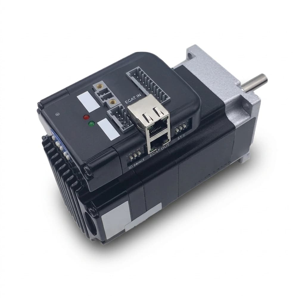
Bus-Controlled Stepper Motors: EtherCAT, CANopen, and Modbus RTU vs. Pulse/Direction Sourcing Guide
Compare bus-controlled stepper motors: EtherCAT, CANopen, Modbus RTU vs. pulse/direction. Check PLC compatibility, wiring costs, and RFQ acceptance criteria.

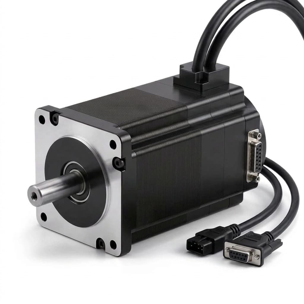
Closed-Loop NEMA Stepper Motors: The 2026 OEM Selection Guide
Use this OEM guide to compare open-loop and closed-loop NEMA stepper motors: torque margins, encoder feedback, BOM tradeoffs, sizing limits, and RFQ checks.
Geared NEMA Stepper Motors: Planetary vs. Spur Gearbox Selection for OEMs
Compare planetary and spur gearboxes for NEMA stepper motors. Learn how to evaluate torque multiplication, backlash, and BOM costs for 2026 OEM automation projects.