Screen a 12V setup against a published voltage guideline, then check the motor-and-driver data that determines usable speed and torque.
Published September 26, 2026 · Last reviewed October 6, 2026
Compare your DC bus with a published inductance guideline; this does not estimate RPM or torque.
The cited Geckodrive G540 accepts 18–50 V DC and cannot run from a 12 V bus. Check the input range of your specific driver.
Use the per-phase inductance from the motor datasheet.
The driver's voltage rating still applies.
Enter the datasheet inductance and your driver's DC bus voltage.
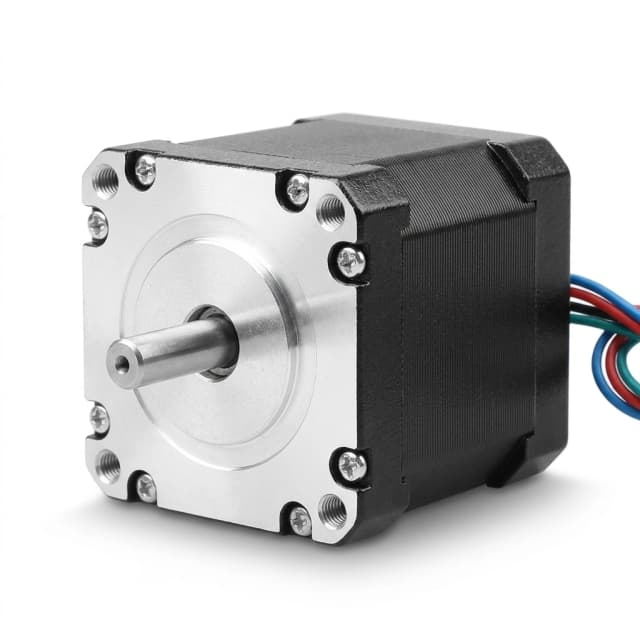
A compatible driver can run a NEMA 23 motor from 12V, but whether it meets an application depends on the exact motor, driver, load, target speed, and acceleration. NEMA 23 names a frame size; it does not define one winding or speed–torque performance.
Decision rule: At standstill, a correctly configured current-regulating driver can reach its set phase current at either bus voltage. At speed, inductance and back EMF make current harder to build; a higher bus can help, but the usable torque must be checked on the exact motor-and-driver curve.
The driver must change winding current as the motor steps. Inductance resists that change, and back EMF rises with speed, leaving less voltage to build current. If phase current falls behind its command, available torque falls too. The size of the effect depends on the motor, driver, settings, and load.
The supply voltage is switched across the motor phase by the driver.
Inductance resists current change; the driver regulates current to its setpoint.
As the motor turns, back EMF reduces the voltage available to change phase current.
If current cannot follow the commanded waveform, available torque falls. The amount is motor- and driver-specific.
The Geckodrive G540 manual gives this supply-voltage rule of thumb, where L is phase inductance in millihenries:
For 4.0 mH, this gives 64 V. That is not an optimum, a torque prediction, or a universal safe limit: the G540 manual lists an 18–50 V DC supply range, so the G540 itself is not compatible with a 12 V bus. Use a driver whose documented input range includes your supply, then use the motor's speed–torque curve to assess performance.
A motor's winding voltage rating is not the same as the driver's DC bus voltage. A current-regulating (chopper) driver switches the bus and regulates phase current toward its configured limit.
A higher bus can make current rise faster, but only within the driver's voltage, current, and thermal ratings. Set the current for the motor's actual wiring configuration; a current limit does not protect a driver from an excessive bus voltage.
References checked October 6, 2026. They support the general mechanism and a product-specific guideline; they do not replace the selected motor's and driver's datasheets. This page reports no physical motor test; the screening tool performs only the published guideline comparison.
Have the motor and driver part numbers, target speed, and load torque? Ask our application team to review the combination.
Ask an application engineerBefore choosing a 12V power supply for cost or convenience, compare full-system cost, performance margin, and ratings.
A move can stall if required load torque exceeds what the motor produces at that speed, especially during acceleration. Compare the operating point with the actual torque curve and test the full motion profile before machining or positioning work.
Motor phase-current ratings are not the same as DC input current. Compare the total bill of materials for the supply, compatible driver, wiring, and protection against the required performance. Follow driver or supply sizing guidance for the number of axes and duty cycle, and verify continuous output under load.
Do not exceed the motor's rated phase current to compensate for weak high-speed performance. Winding copper loss grows approximately with current squared; set the driver for the chosen winding connection and check motor and driver temperature in the real enclosure.
A higher bus voltage can improve current rise and high-speed torque, but it does not guarantee a particular RPM or torque. Select a voltage that fits the motor, driver, supply, and application's measured requirements.
| DC bus | Potential trade-off | What to verify |
|---|---|---|
| 12 V | Less voltage headroom for changing phase current at speed. | The 12 V speed–torque curve at the required load and acceleration. |
| 24 V | More voltage headroom than 12 V may improve current rise. | The exact driver's input limit and the motor curve at 24 V. |
| 36–48 V | Can provide still more voltage headroom; compatibility becomes critical. | Driver maximum, supply tolerance, regeneration handling, and motor curve. |
This is a qualitative comparison, not a torque or speed prediction. Use curves and limits published for the selected motor and driver.
If you're unsure whether your application fits 12V, 24V, or 48V, our engineering team can help you select a suitable NEMA 23 motor and power supply combination.
Inquiry Email
