High-torque stepper motors operating on 12V DC rails face unique physical limitations. Use our interactive simulator below to evaluate dynamic coil impedance (Z), back-EMF speed decay, and safety headroom. Then read the engineering report to compare drivers, identify winding risks, and review installation guidelines. (See also our [12V Geared Stepper Motor](/learn/12v-geared-stepper-motor) sizing guide if you are using gearboxes).
Evaluate how winding impedance ($Z$), back-EMF ($V_{bemf}$), and driver voltage ceilings affect dynamic torque curves. Compare 12V DC against higher voltages in real-time.
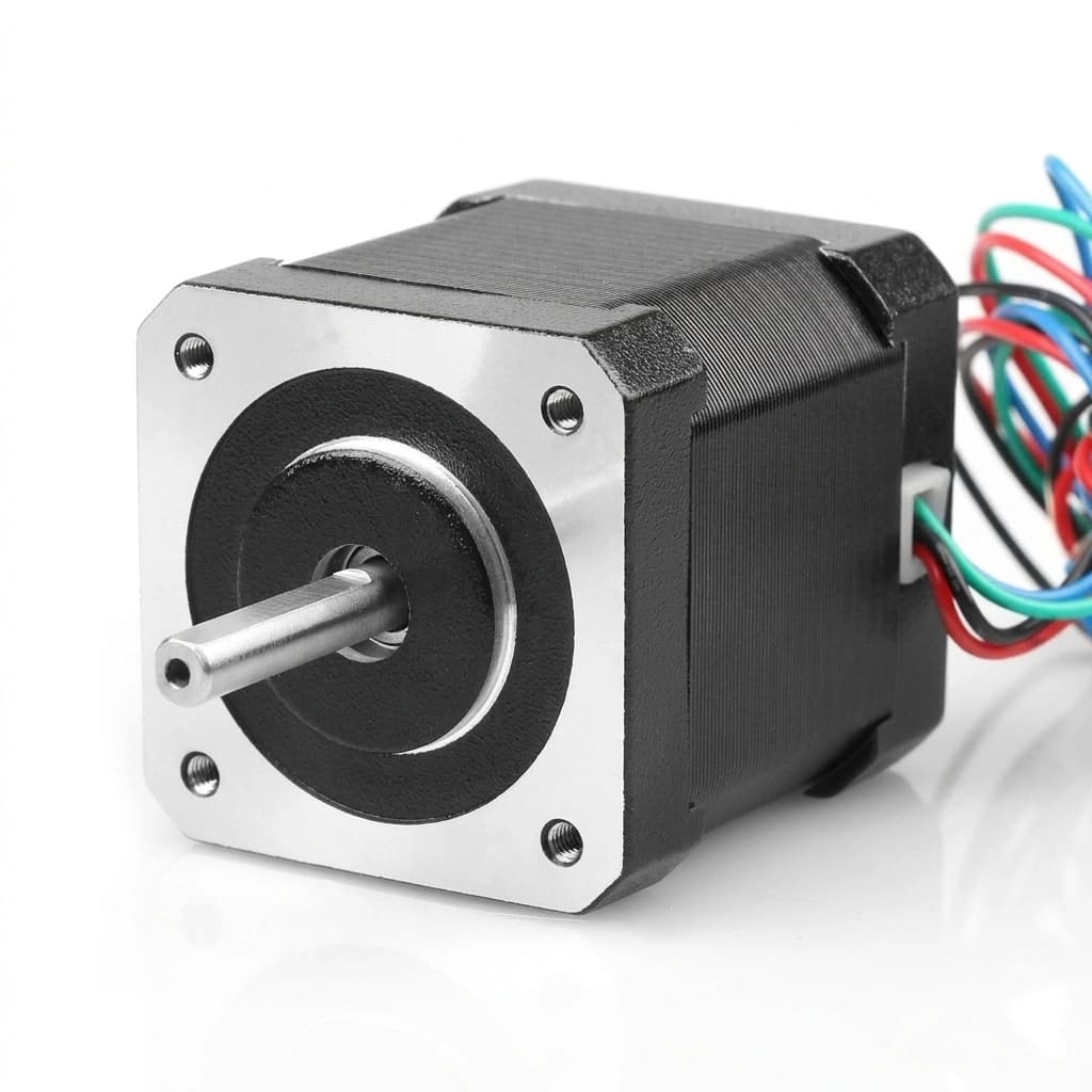
When designing stepper systems, do not rely on static holding torque catalogs. The combination of bus voltage, coil impedance, and back-EMF dictates dynamic performance:
While 12V is safe for low-speed positioning, the low voltage limits the rate of current injection, causing torque to fall off rapidly at higher RPM. Consider 24V or 48V for higher speeds.
Winding inductance dictates current rise time. Low-inductance motors charge faster, maintaining dynamic torque longer under 12V rails compared to high-inductance alternatives.
Low-resistance high-torque steppers draw excessive current without chopper regulation. L298N drivers will overheat and burn out. Use current-limiting chopper drivers exclusively.
Holding torque is measured at 0 RPM. When matching motors to applications, always design with dynamic torque curves and apply a 1.5x - 2.0x torque safety factor.
To understand why a 12V supply causes stepper torque to collapse at higher speeds, we must look at the electromagnetic behavior of the coils. The current rise in a stepper winding is governed by the differential equation:V_bus - V_bemf = L * (dI/dt) + I * RWhere V_bus is the supply voltage, V_bemf is the opposing voltage generated by rotor rotation, L is the coil inductance, and R is the phase resistance.
As the step frequency (f) rises, the inductive reactance increases linearly. Under a 12V rail, this growth in impedance rapidly limits current, choking the motor torque output.
The electrical time constant (\u03c4 = L/R) determines coil charging speed. Standard high-inductance motors charge too slowly at speed, whereas low-inductance coils reach full current quickly.
Rotor rotation generates Back-EMF (V_bemf) that opposes the supply voltage. When V_bemf approaches 12V, the net driving voltage collapses, causing the motor to stall.
Below are data-backed comparison tables to guide your selection of motor sizes, driver configurations, and wiring methods for low-voltage applications.
| NEMA Size | Holding Torque | Rated Current | Inductance (L) | Resistance (R) | Time Constant (\u03c4) | 12V Max Recommended Speed |
|---|---|---|---|---|---|---|
| NEMA 17 (42mm) | 0.42 N.m | 1.5 A | 2.8 mH | 1.5 Ω | 1.87 ms | 220 RPM |
| NEMA 23 (57mm) | 1.26 N.m | 3.0 A | 3.5 mH | 1.2 Ω | 2.92 ms | 140 RPM |
| NEMA 23 Custom | 1.20 N.m | 4.2 A | 1.6 mH | 0.5 Ω | 3.20 ms | 280 RPM |
| NEMA 34 (86mm) | 4.50 N.m | 4.0 A | 6.5 mH | 1.8 Ω | 3.61 ms | 75 RPM |
| Driver Model | Voltage Range | Max Continuous Current | Microstepping Limit | UVLO Level | Thermal Requirements | 12V Application Compatibility |
|---|---|---|---|---|---|---|
| A4988 Carrier | 8.0V - 35V | 1.0 A Continuous | Up to 1/16 | None (~7.5V hard limit) | Mandatory > 1.0A | Light Duty only |
| DRV8825 Carrier | 8.2V - 45V | 1.5 A Continuous | Up to 1/32 | None (~8.0V limit) | Mandatory > 1.2A | Medium Duty |
| TMC2209 Silent | 4.75V - 28V | 1.4 A RMS (2A Peak) | Up to 1/256 interpolation | None (~4.5V limit) | Heatsink required | Precision / Quiet-operation |
| DM542 Industrial | 20.0V - 50V | 3.0 A Continuous | Up to 1/128 configuration | Active (Fails to boot @ 12V) | Self-cooled housing | Heavy Industrial (Needs >=24V) |
| Wiring Method | Equivalent Resistance | Equivalent Inductance | Low-Speed holding torque | High-Speed Dynamic Torque | Current Draw Scaling | 12V Recommendation |
|---|---|---|---|---|---|---|
| Bipolar Parallel | 0.5x R_phase | 1.0x L_phase | 100% Rated | Excellent (Minimized Reactance) | 1.41x Rated Current | Highly Recommended for 12V Rails |
| Bipolar Series | 2.0x R_phase | 4.0x L_phase | 100% Rated | Extremely Poor (4x Impedance Choke) | 0.70x Rated Current | Avoid for speeds > 60 RPM under 12V |
| Unipolar (6-Wire) | 1.0x R_phase | 1.0x L_phase | 70% Rated | Moderate | 1.00x Rated Current | Viable legacy fallback |
Modern chopper drivers maintain constant coil current by regulating power supply output through Pulse Width Modulation (PWM).
By applying a higher voltage to the coil at the start of each step pulse, chopper drivers force a rapid current rise. Once the target current limit is reached, the driver cycles the voltage to prevent overheating.
Decay modes control how the coil energy is managed during PWM OFF cycles. Fast decay flushes energy back to the power rail to support high-speed operation, while slow decay circulates current internally to reduce ripple at low speeds.
Stepper motor performance under low-voltage conditions is highly dependent on both how the coils are wired and how mechanical resonances are managed.
Wiring an 8-lead motor in Bipolar Parallel reduces both resistance and inductance, allowing the coils to charge quickly at high speed. Conversely, Bipolar Series wiring increases impedance, limiting performance under 12V rails.
Stepper motors suffer from natural mechanical resonances, especially in the 50-100 RPM range. Low-cost drivers without active dampening can cause the motor to stall under load. Digital drivers use electronic dampening to smooth these harmonics.
Closed-loop stepper control represents the state of the art in positioning systems. Integrating a feedback encoder ensures the driver can compensate for speed decay and prevent step-loss failures.
By comparing the commanded position with the actual rotor position from the encoder, the driver actively adjusts the current in real time to correct errors and prevent stalling.
A clean wiring layout is vital to avoid noise. Keep high-power supply cables separate from logic signals, and make sure motor connections (A/B phases) are securely routed to prevent H-bridge damage.
The chart below illustrates how supply voltage directly affects the speed at which motor torque begins to decay. Higher voltages provide the necessary headroom to sustain current rise rates as step speeds increase.
These tables compile reference guidelines for sizing safety margins, evaluating microstepping torque, and planning multi-axis power supply current limits.
| Application Load Type | Recommended Safety Margin | Core Sizing Risk Factors | System Sizing Mitigation |
|---|---|---|---|
| Direct Drive Inertial (AGV Wheels) | 2.0x - 2.5x | Peak dynamic acceleration and motor back-EMF must not cause step slip. | Implement S-curve ramp rates. |
| Friction Dominated (Belt Extruders) | 1.5x - 1.8x | Predictable constant load, but resonance spikes can cause desynchronization. | Enable microstep dampening. |
| High Static Lock (Positioning Gates) | 1.3x - 1.5x | Full torque is required at 0 RPM where 12V handles winding charging perfectly. | Add physical electromagnet brake. |
| Microstep Setting | Torque Fraction per Microstep | Resonance Severity | Speed Bottleneck | Acoustic Noise level |
|---|---|---|---|---|
| Full Step (1/1) | 100.00% | Severe | Driver Limit | High |
| Half Step (1/2) | 70.71% | Moderate | Driver Limit | Medium |
| Quarter Step (1/4) | 38.27% | Low | High Speed Controller Cap | Low |
| Sixteenth (1/16) | 9.80% | Minimal | Controller Pulse Frequency Bound | Ultra-low |
| Active System Axis Count | Rated Phase Current | Combined Nominal Sum | Derated Dynamic Supply Limit (1.3x) | Recommended Power Supply Rating |
|---|---|---|---|---|
| 1 Axis (Standard) | 3.0 A | 3.0 A | 3.9 A | 5.0 A Source |
| 2 Axes Link | 3.0 A | 6.0 A | 7.8 A | 10.0 A Source |
| 3 Axes Link | 3.0 A | 9.0 A | 11.7 A | 15.0 A Source |
| 4 Axes (CNC Quad) | 3.0 A | 12.0 A | 15.6 A | 20.0 A Source |
Explore these real-world case studies demonstrating proper sizing and optimization for 12V DC stepper motor applications.
Review these deep-dive technical explanations covering motor impedance, dynamic current rise, and driver protection parameters.
If your application requires a custom low-inductance winding configuration, optimized shaft styles (D-cut, keyed, ball screw), or custom current levels, submit an RFQ today. Our engineering team will match your torque curves to a complete motor-driver-supply package.
Inquiry Email
The data and formulas in this guide are derived from the following industry sources:
Page last updated on: 2026-06-20. Winding parameters are reviewed continuously against standard factory batch logs.
